Building a Receiver
A practical build reference for assembling a complete receiver box like we used in the 2025 marching band season. This build utilizes a Raspberry Pi Pico development board and a solderable breadboard in place of the PicoLume Receiver.
Components
A sample bill of materials for building a complete receiver box.
| Component | Vendor | Link | Cost |
|---|---|---|---|
| LED Strip | Amazon | https://a.co/d/5dZHCsu | $39.99 |
| Enclosure | Amazon | https://a.co/d/aFUoaTz | $16.00 |
| Battery | Amazon | https://a.co/d/6rGyLlP | $38.00 |
| Data Connector | Amazon | https://a.co/d/aHqx2SY | $10.00 |
| 5v DC-DC Converter | Amazon | https://a.co/d/dWnYq2U | $1.20 |
| OLED | Amazon | https://a.co/d/1S7XhvB | $2.50 |
| Pi Pico | Digikey | https://www.digikey.com/short/fr7nqzwm | $6.00 |
| Terminal Connectors | Amazon | https://a.co/d/93Ua2sq | $1.00 |
| Polyfuse | Digikey | https://www.digikey.com/short/vtd02qfh | $0.65 |
| Button | Amazon | https://a.co/d/11AqY5U | $0.10 |
| PCB Prototype Board | Amazon | https://a.co/d/7obPzD3 | $1.60 |
| Headers | Amazon | https://a.co/d/4tLLc20 | $0.40 |
| Resistor | Digikey | https://www.digikey.com/short/z1fjbc70 | $0.10 |
| Hookup wire | Amazon | https://a.co/d/cU6Uan1 | $0.50 |
| Level Shifter | Digikey | https://www.digikey.com/short/jm3qfmh9 | $0.80 |
| RFM69HCW Module | Adafruit | https://www.adafruit.com/product/3070 | $9.95 |
| Antenna Edge Connector | Adafruit | https://www.adafruit.com/product/1865 | $2.50 |
| 915 MHz Antenna | Amazon | https://a.co/d/bxBZiUc | $3.00 |
| 24v DC-DC Converter | Amazon | https://a.co/d/3thSwrx | $5.00 |
| Power Button | Amazon | https://a.co/d/5dZHCsu | $0.75 |
| Fuse | Amazon | https://a.co/d/dsVF8H6 | $0.90 |
| Wago Connectors | Amazon | https://a.co/d/3uVVyHP | $1.00 |
| 18 Gauge 3 Conductor Wire | Amazon | https://a.co/d/3TratV2 | $1.00 |
| Velcro | Amazon | https://a.co/d/fQtGbKb | $1.00 |
Interconnect
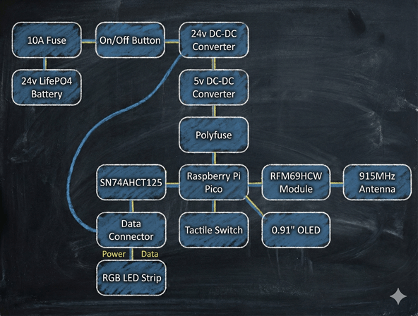
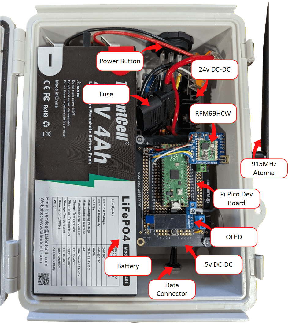
High Level Receiver Interconnect
- 1 The 24V LiFePO4 battery is directly connected to a 10A automotive fuse on the positive rail.
- 2 The output of the fuse is then connected to a rocker switch to turn the receiver on and off. The rocker switch also requires a ground connection for its indicator LED to work. Use Wago connectors to form a ground bus from the battery's negative terminal and distribute ground to the various components.
- 3
The rocker switch then connects to the positive input of an adjustable 8A buck converter. The negative input comes from the ground bus (Wago). Set the converter output to 23.5V.
Note: Using a buck converter here is a trade-off. A better option is a buck/boost converter, which would allow the LEDs to operate down to a much lower battery voltage. A buck-only setup means the converter can no longer regulate once the battery drops below ~23.5V, so LED performance will degrade or stop. In practice, this still provides roughly an hour's worth of continuous runtime. The advantage of the buck converter is cost: these units are about $5 on Amazon, while buck/boost converters cost significantly more (but can extend runtime to two or three hours).
- 4 The 23.5V buck converter output provides power to the LED strip's positive and negative terminals and feeds the input of the 5V DC-DC converter.
- 5
The 5V DC-DC converter (also an adjustable buck) supplies power to the Pi Pico controller.
Note: Adjust the 5V DC-DC converter down to 5.0V before connecting anything. Many units ship set to 20V+ and can destroy a Pi Pico development board.
- 6 A small through-hole polyfuse is used on the positive rail going to the Pi Pico and RFM69HCW radio module. This helps protect the boards against electrical shorts.
- 7 The Pi Pico controller is a combination of the prototype board, level shifter, OLED, tactile switch, and terminal blocks.
- 8 The Pi Pico controller is connected to the 5V DC-DC converter through the polyfuse for power input. It connects to the data line of the RGB LED strip, and the radio module is wired directly to the SPI interface.
- 9 A 0.91-inch OLED display is connected to the I2C interface of the Pi Pico. This is the primary method for displaying state information to the user.
- 10 The data line and power to the LED strip are provided out of the box via a three-pin connector. The male side is mounted to the enclosure and the female side is attached to the LED strip.
- 11
The radio module connects to the enclosure and provides a bulkhead connection for an external 915MHz antenna.
Note: It is also possible to mount a smaller 915MHz antenna inside the enclosure instead of mounting it externally as shown.
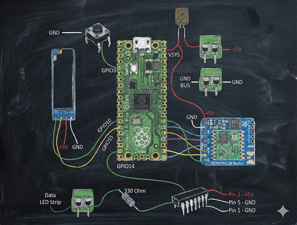
Controller Interconnect